How to find the best position of vacuum valve in die casting mold?
Release time:2023-10-18
How to find the best position of vacuum valve in die casting mold?
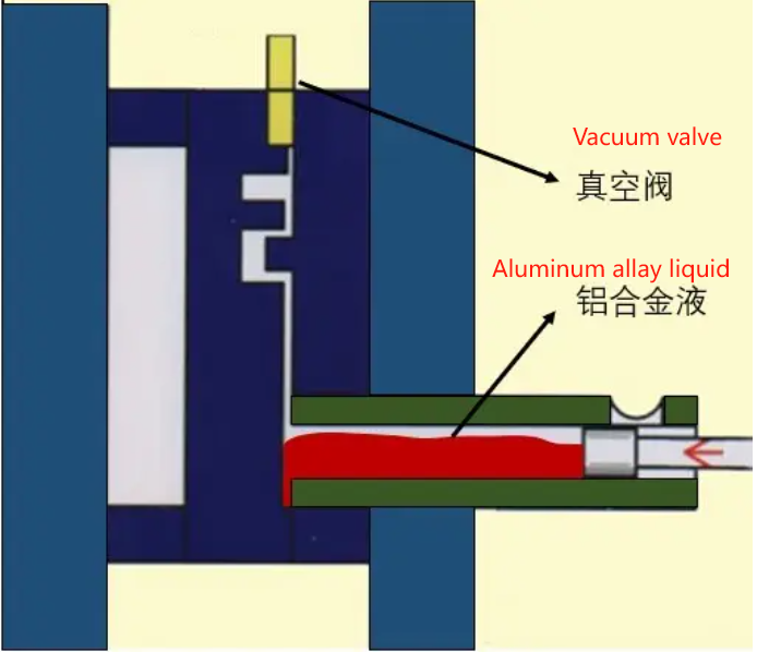
Compared with sand and gravity casting, the microstructure of traditional die casting is not satisfactory, mainly because the jet of high-speed metal flow at the gate is more accessible to the air in the mold cavity than when the metal is slowly fed into the sand or metal mold cavity. The focus of the vacuum die casting process is to minimize this gas-liquid contact, so the effective discharge of the gas in the cavity is the key to the design of the vacuum die casting mold.
For die casting molds, there is no essential difference between traditional exhaust design and vacuum exhaust design, only in the way of exhaust, the former is passive exhaust, using metal flow to discharge the gas, the so-called positive pressure injection; The latter is active exhaust, that is, by using a vacuum device, the gas in the cavity is extracted, also known as negative pressure injection. In terms of exhaust effect, the two are far apart, and the correct vacuum exhaust application will greatly reduce the gas content in the cavity, thereby effectively improving the quality of the product.
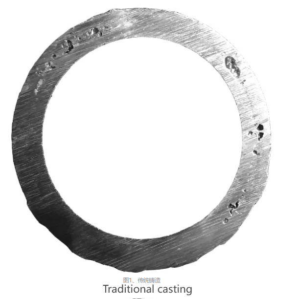
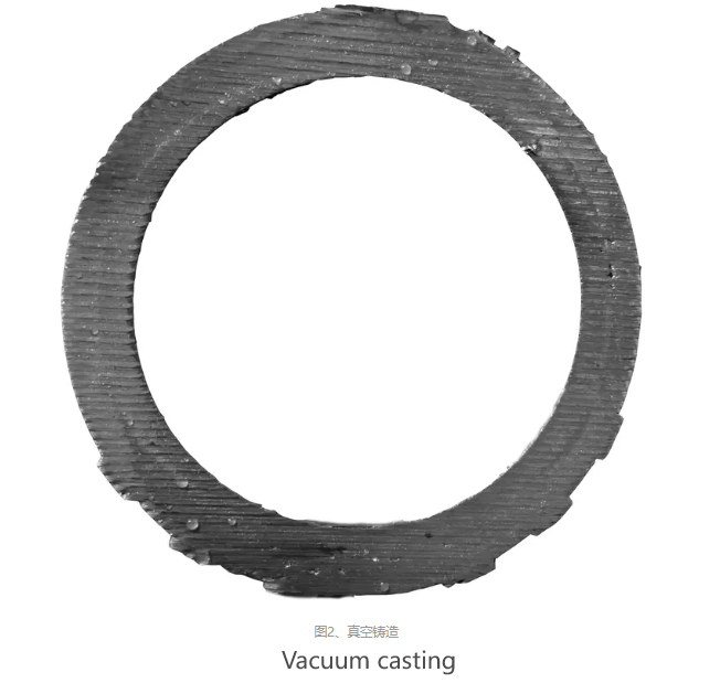
This paper discusses the location of the vacuum valve involved in the design of the vacuum mold scheme, focusing on whether the vacuum valve is better to be far away from the inner gate or close to the gate.
In the design process of vacuum die casting mold, the position of the vacuum valve should be able to keep the vacuum valve open for a long time in order to extract as much gas as possible.
The vacuum valve must be positioned where the alloy melt is last filled, but this position may be counterintuitive, as shown in Figure 3: As with conventional die casting, vacuum die casting presents an atomization flow, and if the vacuum valve is positioned farthest from the gate, it may close early in the cavity filling process.
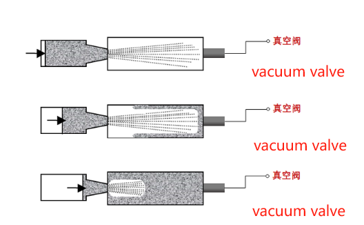 Figure 3. The vacuum valve is located far away from the gate
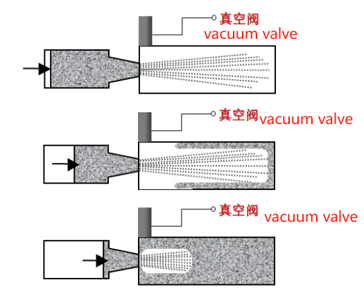 Figure 4. The vacuum valve is located far away from the gate
In order to graphically illustrate the above views, two targeted models are designed. As shown in FIG. 5 and 6 below, die-casting mold filling simulation is carried out on the cloud computing platform to observe the flow of alloy molten liquid in the mold cavity and intuitively understand the difference between the two vacuum valve position layouts in the actual die-casting process.
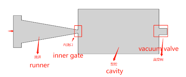 FIG. 5
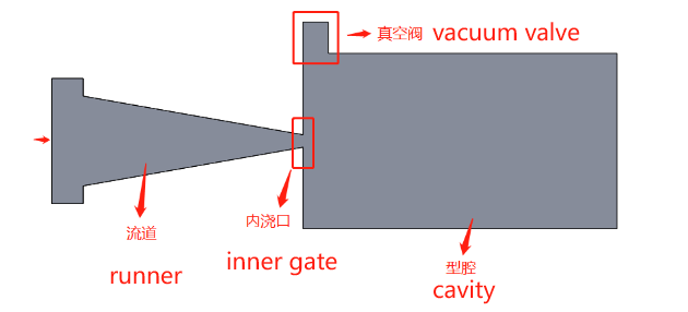
FIG. 6
Comparison of cloud simulation results :
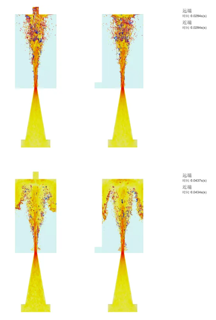
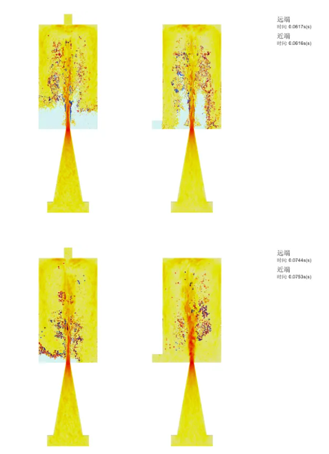
When the example vacuum valve on the left is located far from the gate, the vacuum valve is blocked at the beginning of the filling stage. When the example vacuum valve on the right is located near the gate, the vacuum valve can continue to function during the filling process
It can be seen that the design of the vacuum valve in Figure 5 is indeed counterintuitive, and the vacuum valve in Figure 6 is blocked when the metal filling begins, while the vacuum valve in Figure 6 can be kept open to the maximum and gain valuable time for the vacuum exhaust (roughly 40ms in this example). Of course, this model example is relatively simple, in the actual design and development work, the position design of the vacuum valve can be determined by the powerful die casting simulation capability of the "wise casting cloud" die casting cloud computing platform.

